A progressing cavity pump is a type of positive displacement pump and is also known as a progressive cavity pump, progg cavity pump, eccentric screw pump or cavity pump. It transfers fluid by means of the progress, through the pump, of a sequence of small, fixed shape, discrete cavities, as its rotor is turned. This leads to the volumetric flow rate being proportional to the rotation rate (bidirectionally) and to low levels of shearing being applied to the pumped fluid.
These pumps have application in fluid metering and pumping of viscous or shear-sensitive materials. The cavities taper down toward their ends and overlap. As one cavity diminishes another increases, the net flow amount has minimal variation as the total displacement is equal. This design results in a flow with little to no pulse.
It is common for equipment to be referred to by the specific manufacturer or product names. Hence names can vary from industry to industry and even regionally; examples include: Moineau (after the inventor, René Moineau). The original 4 Manufacturing licenses were issued to; MOYNO pump [Americas], Mono pump [UK, Europe], Gardier [Belgium] and PCM.
A progressing cavity rotor and stator can also act as a motor (mud motor) when fluid is pumped through its interior. Applications include directional well drilling.
progressive cavity pump working principle
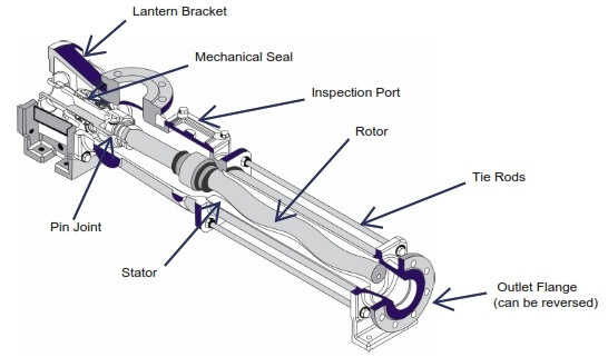
The helical rotor and the two universal joints of the drive mechanism.
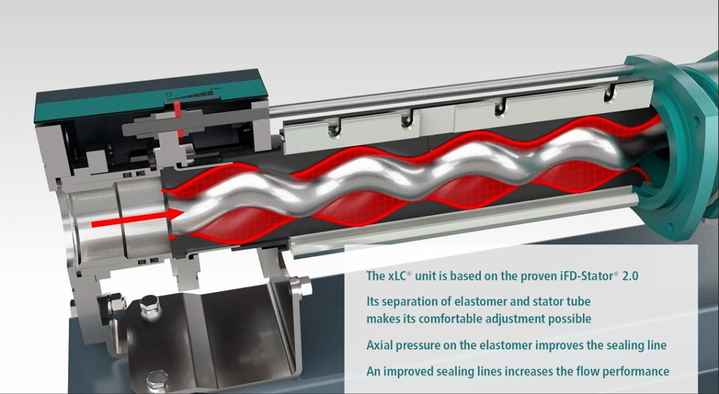
A cutaway drawing of the rubber stator.
Shape of the cavities left between the rotor and the stator.
The progressing cavity pump normally consists of a helical rotor and a twin helix, twice the wavelength helical hole in a stator. The rotor seals tightly against the stator as it rotates, forming a set of fixed-size cavities in between. The cavities move when the rotor is rotated but their shape or volume does not change. The pumped material is moved inside the cavities.
The principle of this pumping technique is frequently misunderstood. Often it is believed to occur due to a dynamic effect caused by drag, or friction against the moving teeth of the screw rotor. In reality it is due to the sealed cavities, like a piston pump, and so has similar operational characteristics, such as being able to pump at extremely low rates, even to high pressure, revealing the effect to be purely positive displacement. The rotor “climbs” the inner cavity in an orbital manner (see pump).
At a high enough pressure the sliding seals between cavities will leak some fluid rather than pumping it, so when pumping against high pressures a longer pump with more cavities is more effective, since each seal has only to deal with the pressure difference between adjacent cavities. Pump design begins with two (to three) cavities per stage. The number of stages (currently up to 24) is only limited by the ability to machine the tooling.
When the rotor is rotated, it rolls/climbs around the inside surface of the hole. The motion of the rotor is the same as the planet gears of a planetary gears system. As the rotor simultaneously rotates and moves around, the combined motion of the eccentrically mounted drive shaft is in the form of a hypocycloid. In the typical case of single-helix rotor and double-helix stator, the hypocycloid is just a straight line. The rotor must be driven through a set of universal joints or other mechanisms to allow for the eccentricity.
The rotor takes a form similar to a corkscrew, and this, combined with the off-center rotary motion, leads to the alternative name: eccentric screw pump.
Different rotor shapes and rotor/stator pitch ratios exist, but are specialized in that they don’t generally allow complete sealing, so reducing low speed pressure and flow rate linearity, but improving actual flow rates, for a given pump size, and/or the pump’s solids handling ability.
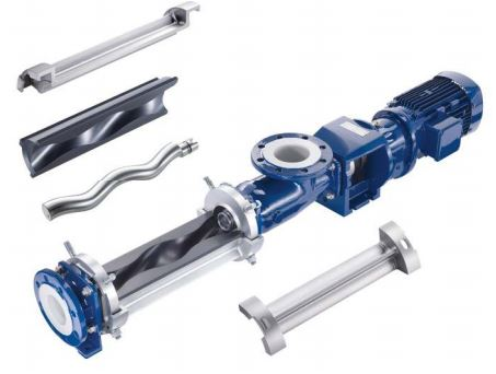
Typical design
Specific designs involve the rotor of the pump being made of a steel, coated with a smooth hard surface, normally chromium, with the body (the stator) made of a molded elastomer inside a metal tube body. The elastomer core of the stator forms the required complex cavities. The rotor is held against the inside surface of the stator by angled link arms, bearings (immersed in the fluid) allowing it to roll around the inner surface (un-driven). Elastomer is used for the stator to simplify the creation of the complex internal shape, created by means of casting, which also improves the quality and longevity of the seals by progressively swelling due to absorption of water and/or other common constituents of pumped fluids. Elastomer/pumped fluid compatibility will thus need to be taken into account.
Two common designs of stator are the “equal-walled” and the “unequal-walled”. The latter, having greater elastomer wall thickness at the peaks allows larger-sized solids to pass through because of its increased ability to distort under pressure. The former have a constant elastomer wall thickness and therefore exceed in most other aspects such as pressure per stage, precision, heat transfer, wear, and weight. They are more expensive due to the complex shape of the outer tube.